

Our tube software
Tube testing
The development of TeZetCAD tube software makes it possible to measure the most complex geometries in both conventional and free-form tube bending. Our comprehensive hardware and software package addresses all tube testing measurement tasks.
Reverse Engineering
TeZetCAD doesn't require any master background data. Sample tubes can be measured directly, regardless of the metrics method applied — tactile probes, laser line, or laser scanning. Immediately after completion of the measurement process, you receive comprehensive documentation of the X, Y, Z, and LRA bending data. The metrics data can then be exported as a STEP/IGES file and drawings can also be created.
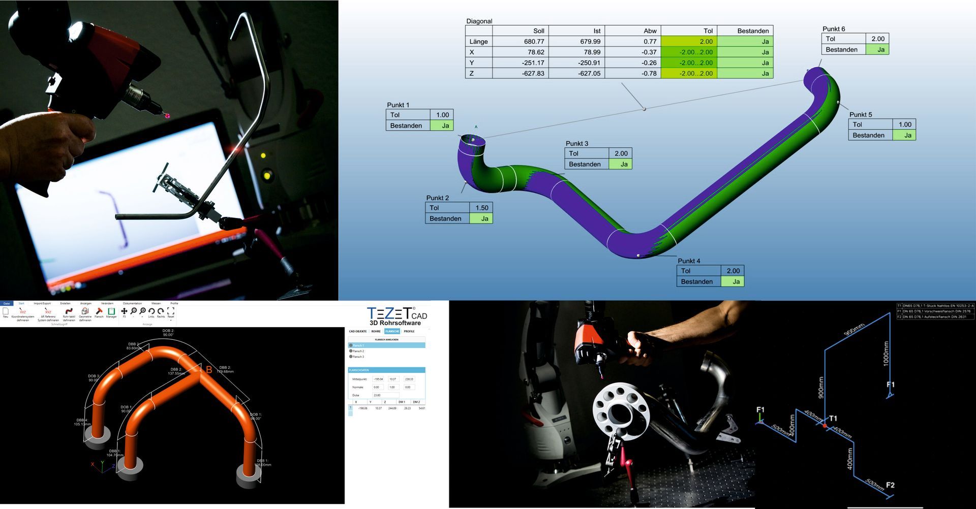
Tube inspection
By creating measurement plans, any measured tube can be immediately compared with the target data from a 3D CAD model or technical drawing. You receive customisable documentation containing detailed information about deviations, tolerances (e.g. shell tolerances or DIN/ISO 2768), and correction data for the bending machine. Thanks to a compatible interface, the correction data can then be sent directly to the bending machine.
Design
On both assemblies and consoles, you can precisely measure the connection points. You can then design your tube in the space between these connection points using a measuring system, or import a CAD tube and adjust the connections. With Apple's Augmented Reality feature, you can view your tube live directly on the assembly or console. You can then either receive an isometric drawing incorporating the X, Y, Z, and bending data, or send the data direct to a bending machine.
Attachments
Whether it's flanges, retaining plates, or tube holes – you can measure all positions precisely and compare them with a 3D CAD model. Accurately measuring and comparing your metrics with a model means you can ensure all components are correctly positioned and meet your requirements. Furthermore, you receive customisable documentation containing detailed information about deviations and tolerances to ensure compliance with quality standards.
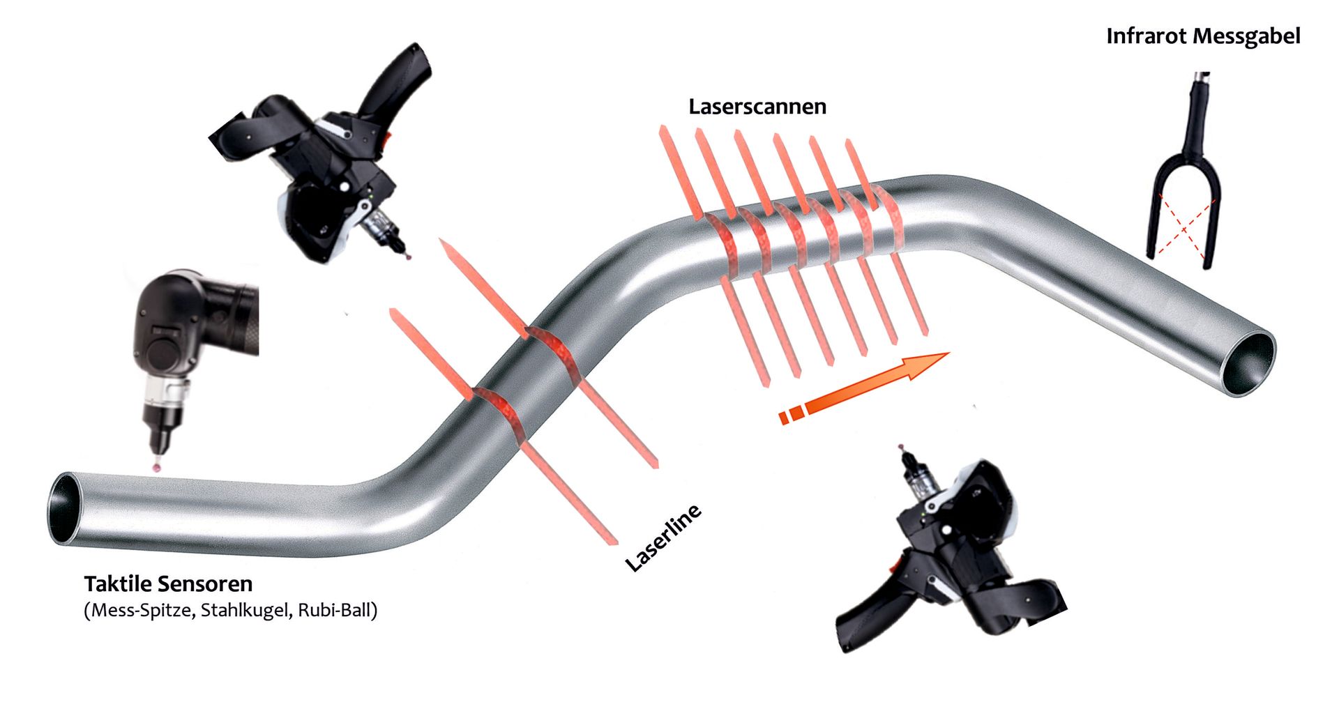
Measurement methods
TeZetCAD offers a variety of measurement methods for tube measurement to meet different requirements and applications. Here are the four principal methods TeZetCAD uses:
Tactile measurements
This method uses a physical probe to precisely measure the tube surface. The positions of all the contact points are recorded to determine the exact tube geometry. Three-point plane measurements are taken at the beginning and end of the tube, while six measurement points are recorded on each straight tube section. This method is particularly suitable for tubes with constant bend radii.
Infrared measurement
This method uses a non-contact infrared fork to precisely measure the tube surface. The positions of the measuring points are recorded to accurately determine the tube geometry. The measurement process begins with the fork being inserted at the beginning of the tube, followed by two measurements at each straight section, and ends with a final insertion at the end of the tube. This method is particularly suitable for tubes with constant bend radii.
Laserline measurement
This method uses a laser beam to project a line onto the tube surface, while a camera captures the reflection and creates a precise profile of the tube geometry. Thanks to fast and highly accurate laser line measurement, this method is ideal for inspecting tubes in production. The measurement is performed by immersion at each straight tube section and at the tube end – similar to a tube measuring fork. This method is particularly suitable for tubes with constant bend radii.
Laser scan measurement
This method uses a laser beam to continuously scan the entire tube surface, including the beginning and end sections. This creates a point cloud containing the acquired measurement data, which is then converted into a representation of the tube geometry. This process is suitable for tubes with constant bend radii and is also an ideal solution for capturing freeform 3D bent tube profiles.
Innovations and interfaces
We continuously monitor market innovations and integrate them into our software. Furthermore, TeZetCAD is renowned for its ability to integrate any type of bending machine into the software.
Tube alignment and new documentation
New to TeZetCAD are special fittings between the measurements and the target tube, which can now also be matched to cylinder axes or cylinder sections. In addition, expanded documentation functions enable the precise determination and targeted control of distances in X, Y, Z, cylinder axes, bends, and much more.
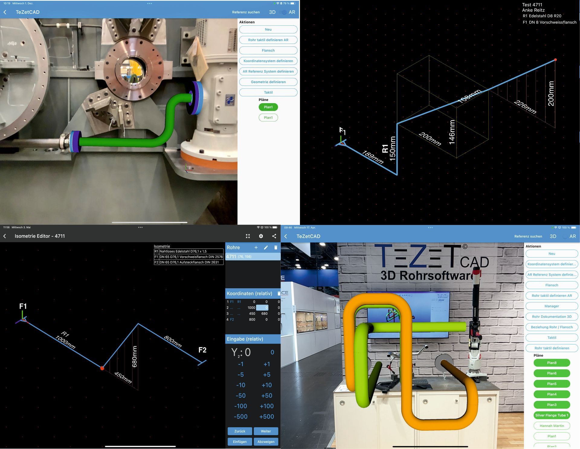
Module design with augmented reality function
With TeZet's expanded functionality, tube runs on a unit can be precisely defined. New features enable tube runs to be designed parallel to each other, allowing interfering geometries to be taken into account in advance. One highlight is the TeZetCAD app which allows you to view the entire tube run in real time using the augmented reality (AR) functions on an iPad or iPhone.
Isometric mode
With the new TeZetCAD app, you can create isometric drawings directly on your iPhone or iPad and convert them into X, Y, and Z coordinates. Next, draw effortlessly with your finger or an Apple Pencil to add connecting elements. Then, transfer the drawings to the desktop version to view them on your computer and convert them into a 3D tube model.
Cutting bending machines
Existing connections: